Introduction
The starting air compressor is a piece of machinery that most engineers give relatively little attention — until it fails. On a ship with a two-stroke main engine, the starting air system is not an auxiliary — it is the primary means of getting the main engine running. Without sufficient air pressure in the starting air receivers (typically 25–30 bar), a two-stroke engine cannot start, and a vessel without propulsion is a vessel in distress.
Starting air compressors are mechanically straightforward: reciprocating, multi-stage, air-cooled or water-cooled piston compressors. But their simplicity belies the precision required in their operation and maintenance. A compressor that delivers air contaminated with water and oil will corrode the starting air system and create the risk of a starting air line explosion — one of the more serious fire hazards aboard a motor vessel. This guide provides the complete maintenance framework that experienced marine engineers use to keep this critical system reliable.
The Role of the Starting Air Compressor in the Main Engine Starting System
Before examining maintenance procedures, it is worth understanding what the compressor must deliver and why the air quality is as important as the air quantity:
- Pressure requirement: The starting air receivers must be maintained at 25–30 bar. Below 17–18 bar on many engines, there is insufficient air pressure to overcome the engine's compression and overcome friction during the first revolution.
- Volume requirement: A slow-speed two-stroke main engine consumes a significant volume of air during the starting sequence. The receiver capacity must cover multiple starts — regulations require a minimum of 12 consecutive starts on the main engine receivers.
- Air quality requirement: Moisture in the starting air system causes corrosion in the distribution pipework and, critically, can accumulate as liquid water in the starting air valve chests. During engine starting, this liquid can hydraulically lock the cylinder — an extremely dangerous condition. Vaporised lubricating oil from the compressor can also accumulate and, with the right conditions, ignite explosively in the starting air line — a starting air line explosion.
Daily Inspection Routine
The daily starting air compressor routine should take less than five minutes — but it must be done every day without exception:
- Drain the air receivers and inter-stage separators: Open the drain valves on each air receiver and each inter-stage moisture separator and drain until only clean air escapes. Do not crack the valve and walk away — stand and watch what comes out. Large volumes of water or oily emulsion indicate a problem that needs investigation, not just draining.
- Check lube oil level: Verify the crankcase oil level is between the low and high marks on the sight glass.
- Check cooling water level (if water-cooled): Verify coolant level and check the sight glass for evidence of oil contamination in the cooling water circuit.
- Listen to the running compressor: A healthy air compressor has a distinctive, rhythmic sound. Knocking, rattling, hissing, or changes in the frequency of the unloading cycle are all warnings. This is not a diagnostic procedure — it is a familiarity check. Engineers who know what "normal" sounds like will immediately notice "abnormal."
- Log the inter-stage pressures: If the compressor has inter-stage pressure gauges, log the readings. Rising or falling inter-stage pressure is the earliest and most sensitive indicator of valve condition.
Weekly Inspection Routine
- Check for air leaks across the full system: Use soapy water around the inter-stage connections, valve chest covers, and aftercooler connections. Any bubble formation indicates a leak that must be tightened or resealed.
- Check belt tension and condition (if belt-driven): Inspect V-belts for cracking, glazing, or uneven wear. Check tension by pressing the centre span of the belt — there should be minimal deflection per metre of belt span as specified by the maker.
- Inspect the air filter: Remove and inspect the inlet air filter element. A blocked inlet filter starves the compressor of air, reduces delivery efficiency, and increases suction temperatures — all of which accelerate valve wear and contaminate the air.
- Check and clean the unloader mechanism: The unloader — which opens the suction valve during off-load periods to allow the compressor to motor without compressing air — must operate freely. A sticking unloader causes the compressor to motor under full load continuously, overheating the valves.
- Inspect the safety valve: Manually lift the safety valve (after isolating the system from the receiver) to verify it opens freely and re-seats cleanly. A stuck-shut safety valve is a code violation. A safety valve that refuses to re-seat after manual lifting requires immediate replacement.
Intercooler and Aftercooler Inspection
The intercooler — fitted between compression stages — and the aftercooler — fitted at the final discharge — are among the most critically neglected components on a marine air compressor. Their function is to reduce the air temperature between stages and at delivery, which has two important effects: it increases the compressor's volumetric efficiency, and it condenses and removes moisture from the compressed air before it can carry that moisture into the receivers and distribution system.
When the coolers become fouled with scale, oil deposits, or corrosion products, their cooling efficiency drops. The consequences are serious:
- Increased delivery temperature: Hot compressed air carries more water vapour into the receivers. More moisture accumulates in the system.
- Carbonisation of valve oil: Excessive air temperatures in the valve chambers cause the thin film of lubricating oil on the valve plates to carbonise (burn). Carbon deposits on valve plates are one of the primary causes of valve seat leakage and valve plate breakage.
- Thermal stress on valves: Cyclic thermal loading accelerates fatigue cracking in valve plates.
Coolers should be cleaned chemically (with a descaling solution appropriate for the tube material) or mechanically (rodding through the tubes) according to the maker's maintenance schedule — typically every 2,000–4,000 running hours, or sooner if inter-stage temperatures show a rising trend.
Common Valve Failures and How to Identify Them
The suction and delivery valves are the hardest-working components in a reciprocating compressor. They open and close many thousands of times per hour under high differential pressure, subject to both mechanical and thermal stress. Valve failure is the most common cause of reduced compressor output and high delivery temperatures.
- Broken valve plates: The thin steel or plastic valve plate cracks due to fatigue. Symptoms: sudden loss of output from one stage, metallic debris visible in the valve chest, hot running of that stage. Finding a broken valve plate means the valve chest must be inspected for any fragments that could have entered the air stream.
- Carbon-fouled valve seats: Carbon deposits from carbonised oil build up on the flat seating face of the valve. The deposit acts as a spacer, preventing the valve plate from seating flat and allowing gas to blow back through. Symptoms: gradual loss of inter-stage pressure, increasing delivery temperature, longer time to charge the receiver to full pressure.
- Valve seat erosion: High-velocity gas flow across a slightly leaking valve seat erodes the seat face progressively. Once erosion begins, it accelerates. Symptoms: the same as carbon fouling, but the seat face will show a visible groove or channel when inspected.
- Sticking valve (seized spring): The valve spring that returns the plate to its closed position corrodes or fatigues and ceases to function. A stuck-open valve on the suction side prevents compression. A stuck-open valve on the delivery side allows back-flow. Symptoms: very low output, possibly compressor running hot.
Moisture Problems — Causes and Solutions
Excessive moisture in the starting air system is simultaneously a maintenance problem, a corrosion problem, and a safety problem. Engineers must understand the cause to apply the correct solution:
- Cause — High ambient humidity: Atmospheric air in humid tropical regions carries significantly more moisture than air in temperate or polar climates. More moisture enters the compressor; more draining is required. This is not a failure — it is a condition adjustment. Increase draining frequency.
- Cause — Fouled coolers: If the inter-stage and aftercooler are not reducing air temperature effectively, the dew point of the compressed air remains high. More water vapour stays in suspension and carries through to the receivers instead of condensing at the separator. Solution: clean the coolers.
- Cause — Leaking compressor piston rings: Worn compressor piston rings allow lube oil to be carried over into the compressed air stream. This oil then mixes with condensed water to produce an oily emulsion — the most dangerous form of moisture contamination. Solution: overhaul the compressor piston rings.
- Cause — Blocked moisture separator drains: Automatic drain valves on moisture separators can block with scale or rust particles and fail to drain. The separator then fills with water and liquid water carries over into the distribution system. Solution: check and clean auto-drain valves weekly.
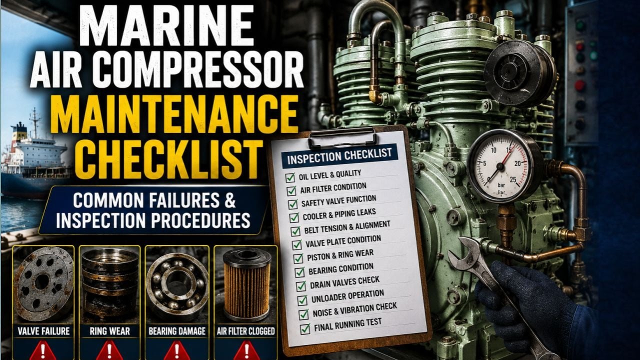
Marine Air Compressor Maintenance Checklist
- ☑ Daily: Drain all receiver and separator drains; log drain volume and character
- ☑ Daily: Check and log crankcase oil level
- ☑ Daily: Check and log inter-stage pressures against baseline
- ☑ Daily: Listen to compressor during operation; note any change in sound or cycle
- ☑ Weekly: Inspect all inter-stage connections and valve chests for air leaks
- ☑ Weekly: Clean inlet air filter
- ☑ Weekly: Check auto-drain valve operation on all separators
- ☑ Weekly: Test safety valve manual lift function
- ☑ 250 hrs: Change crankcase lubricating oil
- ☑ 500 hrs: Overhaul suction and delivery valves — inspect plates, springs, seats; replace worn parts
- ☑ 2,000 hrs: Clean intercoolers and aftercooler — descale tubes; pressure test for leaks
- ☑ 4,000 hrs: Overhaul pistons and cylinder liners — measure piston ring gap and side clearance; replace rings if beyond limits
- ☑ Annual: Survey by class surveyor; review of compressor log book records
- ☑ Continuous: Maintain correct oil level; never allow crankcase to run dry
Troubleshooting Table
Symptom Probable Cause Corrective Action Compressor takes too long to charge receivers to full pressure Worn or carbon-fouled delivery valves; worn piston rings; blocked inlet filter Overhaul valves; measure ring gap; replace inlet filter element Excessive moisture in receivers — large water output at drains Fouled intercoolers; blocked auto-drain valves; high ambient humidity Clean coolers; check auto-drain function; increase draining frequency Oily water at receiver drains Worn compressor piston rings allowing lube oil carry-over Overhaul piston and rings; check oil separator operation High delivery air temperature Fouled aftercooler; broken delivery valve (hot gas back-flow); insufficient cooling water flow Clean aftercooler; inspect all delivery valves; check cooling water circuit Compressor knocking noise Broken valve plate fragments rattling in valve chest; worn crosshead or connecting rod bearing Open valve chests immediately; inspect for foreign material; check bearing clearances Compressor runs but inter-stage pressure is very low Delivery valve in that stage is stuck open (allowing back-flow) Overhaul delivery valves on the low-pressure stage Safety valve lifts at normal operating pressure Safety valve set pressure has drifted low; valve spring fatigued Test and reset or replace safety valve; do not adjust without certified test equipmentFrequently Asked Questions
How do I know if my air compressor needs valve overhaul without opening it?Monitor the inter-stage pressures. A healthy two-stage compressor will show a stable, predictable inter-stage pressure at a given delivery pressure and ambient temperature. If the inter-stage pressure begins rising (delivery valve in the first stage is leaking — gas is returning) or falling (suction valve in the second stage is not opening freely), the valves in that stage need attention. Log inter-stage pressures daily and plot the trend — the trend will reveal deterioration weeks before the output drops noticeably.
What type of oil should be used in a marine air compressor crankcase?This varies by compressor maker and model — never substitute without checking the manual. Most marine reciprocating air compressors specify a mineral-based, non-detergent compressor oil with a viscosity of ISO VG 100 or ISO VG 150. Detergent-based engine oils are specifically not suitable because they prevent water from separating cleanly in the oil, leading to emulsification and inadequate lubrication of the bearing surfaces. Always use the maker's specified grade.
Is it safe to use oil-free compressors for starting air on ships?Oil-free compressors eliminate the risk of oil carry-over into the starting air system, which is a significant safety advantage given the risk of starting air line explosions. However, their maintenance requirements are different — they typically use PTFE-based piston rings that wear faster than lubricated rings and must be monitored more closely. Oil-free compressors are increasingly specified on new tonnage but require training for engineers who are unfamiliar with their maintenance regime.
What is the danger of a starting air line explosion?A starting air line explosion occurs when a mixture of oil vapour and air in the starting air distribution system reaches its ignition point. This can happen if a starting air valve leaks hot combustion gas back into the starting air line (from a failing engine starting valve), providing both the heat source and the ignition point for oil-contaminated air. The explosion propagates through the pipework at high velocity, typically causing catastrophic damage to the air receivers, distribution pipework, and sometimes injuries to crew. Keeping the air clean and the starting valves maintained is the primary prevention.
What is the correct pressure for the main starting air receivers?SOLAS and engine builder recommendations align at a maximum working pressure of 30 bar for main starting air receivers, with a hydrostatic test pressure of 1.5x working pressure (45 bar) at initial commissioning. Receivers must be inspected internally at the intervals required by the classification society — typically every 2.5 years for external and 5 years for internal inspection. The minimum pressure from which a two-stroke main engine can be reliably started is typically around 17–18 bar, though some engine builders specify higher minimum starting pressures.