Introduction
Compression pressure is the single most telling vital sign of a diesel engine's mechanical health. Every experienced marine engineer knows that an engine cannot be properly diagnosed — let alone overhauled — without first establishing a reliable compression baseline. When compression pressure drops below the builder's minimum acceptance limit, the consequences are immediate and cascading: hard starting, reduced power output, abnormal exhaust smoke, and accelerated wear across every component in the combustion chamber.
This guide walks through the complete diagnostic workflow that competent ship engineers follow when confronted with low compression in a marine diesel engine — from interpreting the initial symptoms through root cause identification, measurement procedures, and acceptance criteria. Whether you are dealing with a slow-speed two-stroke main engine or a medium-speed four-stroke auxiliary generator, the diagnostic logic is the same.
What Compression Pressure Actually Tells You
Compression pressure is a direct measure of how effectively the combustion chamber seals the air charge during the compression stroke. In a healthy cylinder, the piston rings, cylinder liner, and valve seats work together to create a gas-tight boundary. When any one of these three sealing surfaces fails, the compressed air escapes — this is called "blow-by" — and the resulting pressure at TDC (Top Dead Centre) is lower than the manufacturer's specification.
The implications are profound:
- Insufficient compression heat: Diesel ignition is entirely dependent on the heat generated during compression. If peak pressure is too low, the fuel-air mixture cannot self-ignite reliably — producing hard starts, misfires, and incomplete combustion.
- Reduced thermal efficiency: A leaking combustion chamber converts less of the fuel's chemical energy into mechanical work, directly increasing fuel consumption.
- Lube oil contamination: Combustion gases escaping past the piston rings into the crankcase carry acidic combustion products and carbon particles, rapidly degrading the crankcase oil and attacking bearing surfaces.
- Accelerated wear cascade: Blow-by increases heat load on piston rings and liner walls, accelerating the very wear that caused the original leak — a self-reinforcing degradation loop.
Recognising the Symptoms of Low Compression
Low compression rarely announces itself cleanly. Engineers typically encounter a cluster of symptoms that, taken individually, could indicate multiple different problems. The skill lies in reading the pattern.
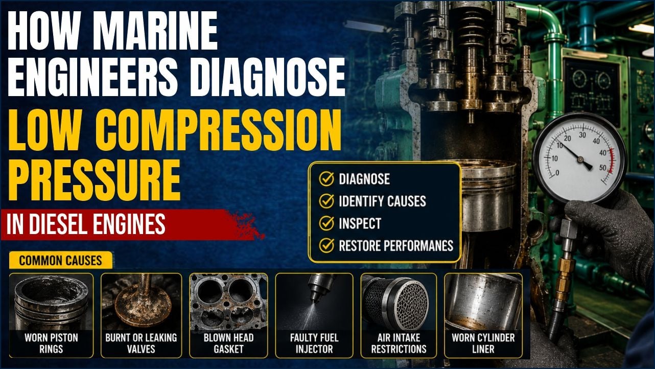
Observed Symptom What It Suggests Severity Extended cranking before start / failure to start Compression too low to achieve self-ignition temperature High White or blue smoke at start-up, clearing after warm-up Oil burning past worn piston rings or valve stem seals Medium–High Black smoke at full load with reduced power output Incomplete combustion due to poor sealing and lost compression heat Medium High crankcase pressure / crankcase relief valve lifting Significant blow-by past piston rings into the crankcase High — stop engine Elevated cylinder lube oil consumption Oil being drawn up past worn rings and burnt in the combustion chamber Medium Low peak firing pressure (Pmax) on indicator cards Direct indication of poor compression — confirms the diagnosis High Abnormally low exhaust gas temperature on one cylinder That unit contributing little power — often from valve leak or ring failure Medium–HighRoot Cause 1: Piston Ring Failure
Piston rings are the primary sealing barrier between the combustion chamber and the crankcase. A four-stroke marine diesel typically has three or more rings per piston — compression rings at the top and oil-control rings below. In two-stroke slow-speed engines, the ring pack can include up to five or six rings, each with a specific function.
Piston ring failure manifests in the following ways that experienced engineers have learned to recognise by sight during overhaul:
- Ring gap wear: As rings wear, the end gap — measured with feeler gauges when the ring is inserted squarely into a worn section of the liner — increases beyond the builder's maximum limit. An excessive ring gap allows direct gas blow-by past the ring without the ring even being damaged.
- Side clearance wear: The groove that the ring sits in wears on its upper and lower faces. Excessive side clearance causes the ring to pump oil and allows combustion gas to bypass the ring's back.
- Ring sticking (carbon lock): Carbon and varnish deposits from degraded cylinder oil or poor combustion bond the rings into their grooves. A stuck ring cannot expand radially against the liner wall — it simply sits in its groove while gas flows freely past it. This is one of the most common causes of low compression in engines operating on heavy fuel oil.
- Ring breakage: A cracked or broken ring loses all sealing function in that section of the liner. Broken ring fragments can also cause catastrophic liner scuffing and piston damage.
- Barrel shape loss: The outer face of a compression ring is precision-ground to a very slight barrel shape to promote hydrodynamic oil film formation. As this profile wears flat, oil film formation collapses and wear accelerates dramatically.
Root Cause 2: Cylinder Liner Wear
Even perfect piston rings cannot create a seal against a worn, out-of-round, or scuffed cylinder liner. The liner is the static sealing surface that the dynamic ring pack must conform to. When the liner exceeds its wear limits, no amount of ring replacement will restore compression.
- Bore gauge measurements exceeding maximum wear limits: Engine builders specify a maximum permissible wear diameter (often expressed as a percentage of the original bore diameter — typically 0.6–0.8% of nominal bore). Once this limit is reached, compression cannot be reliably maintained regardless of ring condition.
- Ovality: Liners wear unevenly, typically more in the fore-aft direction (the thrust and anti-thrust axis). An oval bore means the rings — which are circular — can never fully conform to the bore at the high points, creating permanent leak paths.
- Scuffing and polishing: A glazed, polished liner has lost its cross-hatch honing pattern. Without the microscopic oil-retaining grooves, the oil film between ring and liner collapses, causing metal-to-metal contact and dramatically worsening compression.
- Cold corrosion ridges: In engines operating on high-sulphur fuel with insufficient alkalinity in the cylinder lube oil, sulphuric acid condenses on the liner wall below the piston travel zone, creating a sharp corrosion ridge. This ridge can break rings as the piston approaches BDC.
Root Cause 3: Valve Leakage (4-Stroke Engines)
In four-stroke diesel engines, the inlet and exhaust valves are the third critical sealing boundary. Valve leakage is particularly insidious because it often produces symptoms that closely mimic ring wear — yet the remedy is completely different. Misdiagnosis leads to expensive and unnecessary piston overhauls that fail to cure the problem.
- Burnt exhaust valve seat: The exhaust valve operates in a stream of 500–700°C combustion gas. If the valve and seat do not make a perfect gas-tight contact, localised hot-gas blow-by erodes a "gutter" around the seat contact face. Once this groove forms, it deepens rapidly — a classic runaway failure mode.
- Valve seat recession: Sustained high-temperature operation or operating without seat cooling (in water-cooled seats) causes the seat insert to sink into the head casting, reducing valve lift and degrading seating contact.
- Carbon deposits on valve face: Carbon bridges across the valve seat prevent full closure, holding the valve slightly open during compression. A systematic de-carbonisation of the cylinder head often recovers several bar of compression pressure before any mechanical repair is needed.
- Valve spring fatigue: Weakened valve springs allow valve float at higher engine speeds, preventing full closure and causing compression loss under load that does not appear during cranking-speed compression tests.
Compression Testing Procedure
A compression test is only meaningful if it is performed correctly and consistently. Sloppy technique produces unreliable data. Here is the procedure followed by competent engineers:
- Warm the engine first: Always conduct the compression test after the engine has reached normal operating temperature (cooling water temperature 75–85°C). Cold cylinder bore, cold oil, and cold rings all produce artificially low compression readings. A cold test is an unreliable test.
- Disable the fuel system: Cut off fuel supply to prevent the engine from firing during cranking. On electronically controlled engines, isolate the fuel injector circuit. On mechanically controlled engines, move the governor to stop.
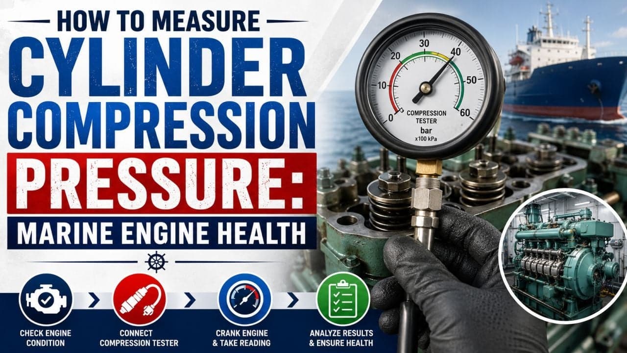
- Install the compression gauge: Remove the fuel injector from the cylinder under test. Install a calibrated compression gauge adaptor in its place. Ensure the adaptor thread is correctly engaged and the gauge is rated for the engine's maximum compression pressure (some marine engines exceed 180 bar at TDC).
- Crank the engine: Using the starting air motor or turning gear (with caution), bar the engine over for at least three to five full revolutions while observing the gauge. The gauge's needle should climb with each revolution and stabilise at the peak value. Record the stabilised value.
- Repeat on all cylinders: Always test all cylinders in the same session with the same gauge. Absolute values matter less than the spread between cylinders — a uniform 10-bar deficiency across all cylinders suggests a general condition (worn rings), while a single cylinder reading significantly lower than the fleet indicates a localised failure (cracked valve seat, broken ring).
- Perform a wet test if low readings are found: Introduce a small amount (10–15 ml) of clean engine oil into the cylinder through the injector port and retest. If the compression reading rises significantly after adding oil (the "oil seal" effect), this confirms that rings and liner are the source of the leakage. If the reading does not change, the valves are leaking. This is one of the most useful and quick differential diagnostic tests available.
Compression Test Troubleshooting Table
Test Finding Most Probable Cause Recommended Next Step All cylinders uniformly low General piston ring wear or liner wear across the engine Measure liner bore; remove one piston and inspect ring condition One cylinder significantly lower than others Localised failure: broken ring, burnt exhaust valve, cracked liner Perform wet test; conduct cylinder head leak test Low reading improves significantly on wet test Rings and/or liner are the primary leak path Overhaul piston and rings; measure liner bore Low reading does not improve on wet test Valve leakage — inlet, exhaust, or both Remove cylinder head; check valve seat contact with engineers' blue Compression rises progressively over 5+ revolutions before stabilising Stuck rings — oil is gradually sealing as the ring frees slightly Treat with ring-freeing compound; plan piston overhaul Compression drops sharply after running for an hour Valve spring fatigue (float at speed) or thermal distortion of valve seat Check valve spring free-length and fitted load; inspect seat contact hotAcceptance Limits and Rejection Criteria
Compression acceptance limits vary by engine design and are always specified in the engine maker's instruction manual. The following figures represent the general ranges for common marine diesel types. Always cross-reference the OEM manual for your specific engine — these values are guides, not universal rules.
Engine Type Typical New Engine Compression (bar) Minimum Acceptance Limit (bar) Max Permissible Spread Between Cylinders (bar) Slow-speed 2-stroke (MAN B&W, Wärtsilä RTA/RT-flex) 130–160 ~85% of new engine value (OEM specific) ± 5–10 bar from fleet average Medium-speed 4-stroke (Wärtsilä 20, MAN L/V series) 45–65 ~75–80% of new engine value ± 3–5 bar from fleet average High-speed 4-stroke auxiliary (Yanmar, Daihatsu, Caterpillar) 30–50 ~70–75% of new engine value ± 2–3 bar from fleet averageCritical rule: The spread between the highest and lowest cylinder reading is as important as the absolute values. An engine where all cylinders read 15% below nominal but uniformly can often run acceptably. An engine where one cylinder reads 30% below the others is a cylinder unit in acute distress that must be investigated immediately.
Compression Testing Checklist
- ☑ Engine warmed to normal operating temperature before testing
- ☑ Fuel supply isolated and confirmed off
- ☑ Calibrated compression gauge with range appropriate for engine (verify last calibration date)
- ☑ Gauge adaptor thread confirmed correct for injector bore size
- ☑ Engine cranked minimum 3–5 full revolutions per cylinder
- ☑ All cylinders tested in same session with same gauge
- ☑ Peak stabilised pressure recorded (not first-revolution value)
- ☑ Wet test performed on any cylinder reading below acceptance limit
- ☑ Test results logged with date, engine running hours, and cooling water temperature
- ☑ Results compared to previous test records and OEM acceptance limits
- ☑ All injector seats and copper washers renewed before reinstalling injectors
Frequently Asked Questions
Why is my marine engine hard to start even though the compression test shows acceptable pressure?Acceptable compression is necessary but not sufficient for reliable starting. Other contributing factors include a defective fuel injector producing poor atomisation at cranking speed, a worn or air-bound starting air motor, contaminated fuel, low ambient temperature reducing lubricating oil viscosity (which increases cranking resistance), or a faulty fuel timing system. Always investigate compression first — but don't stop there if compression is confirmed adequate.
Can I use starting air to spin the engine for a compression test instead of a starting motor?On slow-speed two-stroke main engines, engineers sometimes bar the engine on turning gear with the indicator cocks open to take indicator cards. For a compression test, the engine must be cranked at close to normal starting speed — turning gear is far too slow (a few RPM) and will produce meaningless readings because the heat generated during compression leaks away before the gauge can respond. Use the starting motor or starting air in a controlled way with all fuel isolated.
At what liner wear rate should I plan an overhaul?Most engine builders define a wear rate alarm limit — commonly 0.05–0.10 mm per 1,000 running hours for medium-speed engines. The absolute wear limit (maximum permissible bore diameter) is more critical — typically 0.6–0.8% above the nominal bore diameter. Once either the wear rate trend suggests the absolute limit will be reached before the next planned drydocking, or the absolute limit is reached, overhaul is mandatory. The PMS (Planned Maintenance System) should track liner bore measurements at every piston overhaul.
Can ring sticking be resolved without a piston overhaul?Sometimes. Chemical ring-freeing compounds introduced through the fuel injector port can dissolve carbon deposits and free mildly stuck rings — especially in four-stroke engines. However, if rings have been stuck for a significant period, the liner surface beneath the rings will have suffered adhesive wear (scuffing), and a chemical treatment will reduce blow-by without fully restoring compression. An overhaul is then the only correct solution. Chemical treatment buys time; it is not a permanent fix.
How does heavy fuel oil (HFO) operation affect compression loss rates?HFO contains catalytic fines and sulphur compounds that accelerate both abrasive and corrosive liner wear. Cat-fines (aluminium and silicon oxides from refinery processes) that bypass the purifiers act like industrial grinding paste between ring and liner. Sulphur in the fuel forms sulphuric acid during combustion, which attacks the liner wall if the cylinder oil's base number (BN) is not matched to the fuel's sulphur content. Engineers on HFO vessels must monitor cat-fine content in their fuel samples rigorously and calibrate cylinder lube oil feed rates carefully.
What is the difference between a compression test and an indicator card?A compression test measures the maximum pressure at TDC during cranking speed — it tells you whether the cylinder seals properly. An indicator card (pressure-versus-crank-angle diagram) is taken at normal running speed and gives the complete picture of events throughout the entire engine cycle: compression pressure, peak firing pressure (Pmax), combustion timing, expansion ratio, and exhaust timing. Indicator cards are far more diagnostic than a simple compression test but require a calibrated indicator instrument and can only be taken on engines fitted with indicator cocks.