Introduction
Marine Exhaust Gas Boilers (EGBs), commonly referred to as economizers, are fundamental to shipboard thermal efficiency. By harnessing waste heat from main propulsion engine exhaust gases (temperatures typically ranging between 240°C and 350°C), economizers generate auxiliary steam for fuel tank heating, heavy fuel conditioning, cargo heating, and accommodation services at sea without consuming auxiliary boiler fuel.
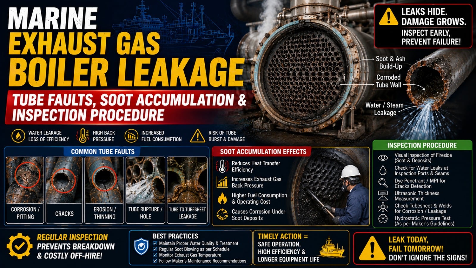
However, when exhaust gas boiler tube leakage develops, the issue goes far beyond losing steam pressure. Escaping water mixes with unburned carbon and sulfur compounds in the exhaust gas stream, forming concentrated sulfuric acid sludge that corrodes adjacent tubes and chokes gas passages. Furthermore, water accumulation creates damp soot beds that ignite into uncontrollable, high-intensity soot fires capable of destroying the entire boiler uptake structure. Prompt diagnosis and systematic tube repair are vital for vessel safety.
Boiler Function & Heat Recovery Designs
Modern commercial vessels utilize several distinct economizer configurations depending on main engine size and steam demand:
- Smoke-Tube Economizers: Hot exhaust gases pass inside the tubes while boiler water circulates around the tube bundle shell. Common on smaller vessels and auxiliary engines.
- Water-Tube & Extended Surface Economizers: Pressurized water circulates inside plain, finned, or pin-type tubes while exhaust gas flows across the outer surfaces. Extended surface pins and fins maximize heat transfer surface area within a compact exhaust uptake footprint.
- Forced Circulation Systems: Boiler circulating pumps draw saturated water from the auxiliary boiler steam drum in the engine room, push it through the exhaust gas economizer coils in the funnel casing, and return a steam-water mixture back to the drum for separation.
Primary Causes of Tube Leakage & Structural Faults
Economizer tube failures originate from both exhaust gas-side and water-side degradation mechanisms:
1. Low-Temperature Sulfuric Acid Dew-Point Corrosion
Heavy fuel oil and VLSFO contain sulfur compounds that combust into sulfur dioxide ($SO_2$) and sulfur trioxide ($SO_3$). In the presence of exhaust moisture, $SO_3$ forms sulfuric acid vapor ($H_2SO_4$). If economizer tube metal temperatures fall below the acid dew point (typically 135°C–145°C)—a common occurrence during slow steaming, port approaches, or low-load operation—acid condenses directly onto the outer tube steel, eating through the metal wall and causing pinhole leaks.
2. Heavy Soot Accumulation and Moisture Absorption
Incomplete engine combustion, slow steaming without auxiliary blower assistance, or defective fuel injectors coat tube banks with oily soot. Soot is highly hygroscopic; when tube leaks or defective soot blower drains release moisture, the soot absorbs the water, forming a thick, acidic, cement-like crust that insulates the tubes, chokes gas flow, and accelerates galvanic pitting.
3. Thermal Stress & Cyclic Fatigue
Frequent engine maneuvering, emergency shutdowns, or feeding cold feedwater directly into hot, dry economizer coils generates severe thermal shock. The resulting thermal expansion and contraction causes metal fatigue, initiating stress cracks at tube-to-header welds and return bends.
4. Gas-Flow Vibration & Fretting Wear
High-velocity exhaust gas pulses generate vortex shedding across tube banks. If tube support baffles, vibration dampers, or clamping plates wear loose, adjacent tubes vibrate against each other or against structural support plates, wearing flat spots and causing mechanical fretting breaches.
5. Water-Side Oxygen Pitting & Scale Accumulation
Improper boiler water chemical treatment allows dissolved oxygen to enter with feed water, causing aggressive localized oxygen pitting from the inside out. Simultaneously, scale deposits insulate the tube inner wall, causing localized overheating and blistering of the carbon steel.
Warning Signs of Exhaust Gas Boiler Leakage
Early identification prevents minor pinhole leaks from escalating into uptake fires. Monitor for these five warning signs:
- Hotwell / Cascade Tank Water Loss: An unexplained drop in boiler feed water tank level, accompanied by continuous feed pump running without visible steam leaks in the engine room, is the classic indicator of an economizer tube leak.
- Acidic Black Water from Economizer Drains: Black, acidic sludge and water constantly discharging from the exhaust uptake drain pot into the funnel bilge or sludge tank confirms water is spraying into the gas stream.
- Rising Exhaust Backpressure & Turbocharger Surging: As wet soot builds up into dense agglomerates between finned tubes, exhaust gas flow passages choke. Backpressure across the engine rises, triggering main engine turbocharger surging and high exhaust temperatures.
- White Steam Plume at Funnel Uptake: A continuous white vapor trail exiting the funnel during sea passage indicates steam vaporization within the exhaust stream.
- Abnormal Gas Temperature Differentials: A narrowing temperature delta across the economizer ($T_{in} - T_{out}$) indicates heavy soot fouling, while an unexpected post-economizer temperature spike can signal the onset of a localized soot fire.
Step-by-Step Inspection Procedure
When tube leakage is suspected, execute this comprehensive inspection workflow:
- Safe Uptake Entry: Stop and lock out the main engine (turning gear engaged, starting air vented). Allow the exhaust uptake to cool below 40°C. Secure forced ventilation and test the atmosphere inside the casing for oxygen content and toxic gases ($CO$, $SO_x$) before entering.
- Visual Inspection of Tube Bundles: Inspect tube banks with high-powered lighting. Look for wet soot "nests," white mineral deposits (boiler water salts), washed-clean shiny tube sections (steam washing), and warped or distorted fins.
- Hydrostatic Pressure Testing: Isolate the economizer from the main boiler drum. Fill the economizer tubes with cold water and pressurize the bundle to 1.25x–1.5x design working pressure using a portable hydraulic test pump. Inspect all tube rows and header joints to pinpoint the exact location of weeping pinholes or ruptured tubes.
- Ultrasonic Thickness (UT) Gauging: Take non-destructive ultrasonic wall thickness measurements on accessible tube bends, straight runs, and header shells. Compare remaining wall thickness against original design tolerances and class minimums.
- Soot Blower Inspection: Inspect soot blower elements, steam lance nozzles, rotating drive chains, and condensate drain traps. Verify that drain valves operate correctly so that wet steam or condensate is never blown into the tube bank during routine soot blowing.
Maintenance Decisions: Clean, Plug, Patch, or Retube?
Depending on the extent and location of tube degradation, select the appropriate engineering resolution:
1. Soot Washing and Cleaning
If tubes are structurally sound but heavily fouled, conduct a thorough water washing using fresh water with an alkaline neutralizing agent (soda ash), keeping uptake drains completely open. Dry the economizer thoroughly by running engine blowers before firing.
2. Emergency Tube Plugging
When a pinhole leak occurs at sea, plug the defective tube to restore steam service until scheduled drydock:
- Fabricate tapered steel plugs (matching boiler tube metallurgy) with a slight taper (typically 1:10 or 1:12).
- Drive the plugs securely into the tube inlet and outlet holes at the header manifold and seal-weld them where required by class regulations.
- Important: Classification societies strictly limit the maximum percentage of plugged tubes (typically no more than 8% to 10% of total heating surface) to avoid overheating and circulation starvation in adjacent tubes.
3. Window Welding & Sectional Cropping
If leakage is isolated to an accessible outer bend or straight section, crop the damaged tube portion. Perform a specialized "window weld" or fit a new certified seamless boiler tube spool piece using full-penetration TIG root and SMAW capping passes, followed by dye penetrant (DPI) and hydro testing.
4. Full or Modular Retubing
When UT measurements indicate general wall thinning exceeding 25%–30% across multiple tube passes or when repeated leaks occur in inaccessible inner rows, replace the entire tube bundle module during a scheduled shipyard repair.
Economizer Troubleshooting Guide
Symptom Likely Root Cause Immediate Action Permanent Correction Feed water loss; wet soot in uptake Tube pinhole leak from acid corrosion Isolate economizer water loop; drain uptake; verify hotwell level Hydro-test; plug defective tube at headers or crop and weld High exhaust gas differential pressure Severe soot blockage across finned tubes Operate soot blowers (ensure dry steam); check engine combustion Open casing in port; fresh-water wash with alkaline neutralizing agent Sudden exhaust temperature spike in funnel Active soot fire ignition in economizer Stop main engine; stop soot blowing; maintain water circulation; boundary cool Inspect for structural damage; retube fire-damaged sections; renew soot blowers Repeated tube leaks at header joints Thermal fatigue; severe vibration; loose baffles Reduce load fluctuation; check circulating pump pressure Re-secure tube support clamps; stress-relieve header welds; renew spools Severe internal tube pitting and blistering Dissolved oxygen in boiler feed water; low pH Test feed water chemical reserve; increase oxygen scavenger dosage Maintain hotwell temp >80°C; retube severely pitted sectionsFrequently Asked Questions
Why must soot blowers never be operated during an active economizer soot fire?Operating steam soot blowers during an active soot fire introduces steam into burning incandescent carbon deposits at temperatures above 700°C–800°C. This triggers the water-gas reaction ($C + H_2O ightarrow CO + H_2$), producing highly flammable carbon monoxide and hydrogen gases that can lead to catastrophic explosive combustion within the exhaust uptakes.
What is the minimum safe feed water temperature for a marine exhaust gas boiler?Boiler feed water entering the economizer should be maintained at a minimum of 80°C to 85°C (and economizer circulating water above 135°C–140°C). This ensures the outer tube surface remains above the sulfuric acid dew point, preventing acidic moisture from condensing on the tube steel during combustion of sulfur-bearing fuels.
How many tubes can be plugged in a marine economizer before class requires retubing?Most classification societies (such as DNV, Lloyd's Register, ClassNK) permit emergency plugging of up to 8% to 10% of total tube heating surface. Exceeding this limit reduces water circulation velocity in remaining tubes, increasing the risk of steam vapor locking, localized overheating, and structural failure.
Why should water circulation never be stopped immediately when an economizer leak occurs?If the main engine is still operating or the uptake casing is hot, stopping water circulation causes the remaining stagnant water in the tubes to flash violently into steam. The uncooled tubes quickly overheat, buckle, and suffer irreversible thermal distortion. Water circulation must be maintained until the engine is stopped and exhaust temperatures fall below 100°C.
How does slow steaming affect exhaust gas economizer reliability?During slow steaming, the main engine operates at reduced load (30%–50% MCR), producing lower exhaust gas flow and cooler gas temperatures (often below 220°C). This leads to incomplete fuel combustion, rapid soot accumulation on finned tubes, and increased condensation of sulfuric acid, dramatically accelerating tube thinning and pitting.
What is the procedure for hydrostatically testing an exhaust gas boiler?Isolate the economizer from the main steam drum with spectacle blinds or certified isolation valves. Fill the economizer with clean deaerated fresh water at ambient temperature (minimum 20°C to avoid brittle fracture). Pressurize the unit using a manual or pneumatic hydraulic test pump to 1.25x to 1.5x working design pressure. Hold the pressure for at least 30 minutes while inspecting all tube passes, return bends, and header welds for pressure drop and moisture weeping.