Introduction
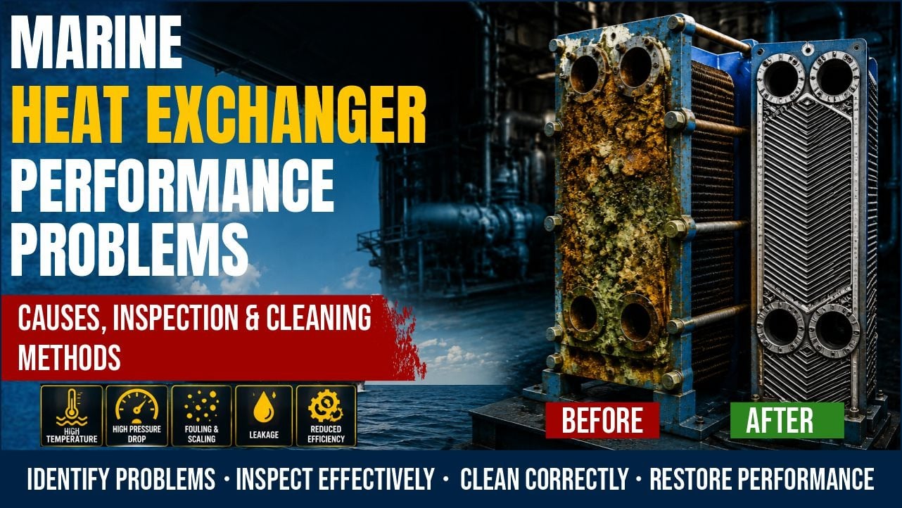
The heat exchangers aboard a motor vessel — the lubricating oil coolers, jacket water coolers, fuel oil heaters, charge air coolers, and fresh water generators — are the thermal management backbone of the entire propulsion and auxiliary system. When a heat exchanger performs below its design efficiency, the downstream effects propagate rapidly: rising lube oil temperatures weaken oil viscosity and accelerate bearing wear; rising jacket water temperatures increase cylinder liner thermal stress; falling charge air cooling efficiency increases combustion temperatures and NOx emissions. Despite their critical role, heat exchangers are consistently among the most neglected items in a ship's planned maintenance system — often because their deterioration is gradual and their failure rarely produces an immediate, dramatic alarm.
This guide addresses that maintenance gap with a systematic framework for understanding, inspecting, and restoring marine heat exchanger performance, drawn from the practical experience of engineers who have seen what happens when this equipment is neglected until the damage is already done.
The Role of Heat Exchangers in Marine Engine Systems
Marine diesel engines produce enormous quantities of heat — only approximately 35–45% of the fuel's energy becomes mechanical output. The remainder must be managed: transferred to seawater, used for heating, or wasted. Heat exchangers are the mechanism through which this energy is managed efficiently.
The major heat exchangers in a typical motor vessel engine room include:
- Lube oil cooler: Maintains engine lube oil temperature at 45–60°C for main engines and 55–70°C for medium-speed auxiliaries. Oil above its design temperature loses viscosity and cannot support the hydrodynamic film in bearings.
- Jacket water cooler (HT/LT central cooler): Maintains jacket cooling water at 70–85°C. Overcooled jacket water causes cold corrosion; overheated jacket water risks boiling and cavitation in the water jacket.
- Charge air cooler (intercooler/aftercooler): Reduces turbocharger delivery air temperature from ~200°C to 40–50°C. Cooler charge air is denser — it carries more oxygen per stroke, increasing power output and reducing thermal loading on pistons and valves.
- Fuel oil heater: Raises heavy fuel oil viscosity to the 13–17 cSt required for efficient atomisation in the injectors. Under-heating causes poor atomisation; over-heating causes vapour lock in the fuel system.
- Fresh water generator (evaporator): Uses jacket water waste heat to distil seawater into potable water. Performance is directly tied to jacket water temperature and seawater cooling quality.
How Reduced Cooling Efficiency Manifests
Heat exchanger performance decline is gradual — and that is precisely what makes it dangerous. Engineers acclimatise to "slightly higher" temperatures and reset alarm setpoints upward rather than investigating the cause. Recognising the pattern of decline before it becomes a crisis requires systematic trending:
- Rising outlet temperature trend: The most direct indicator. If the lube oil cooler outlet temperature is trending 1–2°C higher per month at the same load and seawater inlet conditions, the cooler is losing efficiency. A single elevated reading is noise; a consistent trend is a signal.
- Increased seawater pump differential pressure: Scale deposits on the seawater side of tube-type coolers narrow the effective flow path, increasing resistance and reducing flow — which further reduces heat transfer efficiency.
- Reduced fresh water generator output: A fresh water generator that is producing 20% less daily distillate than its design capacity almost always indicates fouling of the evaporator bundle or insufficient driving temperature from the jacket water system.
- Engine reaching thermal limits at lower loads: An engine that previously ran at 85% load comfortably but now requires load reduction to stay within lube oil temperature limits is revealing a heat exchanger that can no longer keep up — even though the load has not changed, the efficiency of heat rejection has declined.
Root Cause 1: Biofouling and Organic Deposits
The seawater side of every cooler is in contact with a living marine environment. Micro-organisms, algae, barnacle larvae, and marine worms all colonise heat exchanger tubes, particularly in warm tropical and subtropical waters. A biofouling layer just 1–2 mm thick can reduce heat transfer efficiency by 25–40% because the biological material is a poor thermal conductor and also restricts seawater flow through the tube bundle.
Biofouling is most severe in port or during slow steaming in warm, nutrient-rich coastal waters. It is less severe in open-ocean deep water passages. Engineers should schedule cooler inspections after prolonged port stays in tropical ports rather than only on calendar intervals.
Root Cause 2: Scale and Mineral Deposits
When seawater is heated as it passes through the cooler, dissolved minerals — principally calcium carbonate and magnesium salts — precipitate out of solution and form a hard, crystalline scale layer on the tube walls. Unlike biofouling, scale is mechanically hard and thermally very resistant — its insulating effect is greater than organic fouling for the same deposit thickness.
Scale formation accelerates with increasing seawater temperature and in regions with high salinity (e.g., the Persian Gulf and Red Sea, where surface salinity significantly exceeds ocean average). Operators in these regions should plan cooler cleaning intervals at roughly half the frequency used in temperate waters.
Root Cause 3: Tube Leakage
Tube leakage — the failure of one or more heat exchanger tubes, allowing the high-pressure side fluid to contaminate the low-pressure side — is a qualitatively different problem from fouling. Fouling degrades performance gradually; tube leakage contaminates systems that must be kept separate.
The consequences depend on which side is which:
- Seawater into lube oil (lube oil cooler): Seawater contamination of lube oil is catastrophic. Even a small amount of water in lube oil forms an emulsion that destroys the oil's viscosity and its ability to separate bearing surfaces. A lube oil sample showing water contamination must be treated as an emergency.
- Seawater into fresh water cooling circuit: Chloride contamination of the jacket cooling water circuit causes rapid corrosion of the aluminium cylinder heads, wet liner O-ring seats, and the engine block itself.
- Jacket water into lube oil: Fresh water in the lube oil destroys the oil and causes corrosion of bearing surfaces. This is a common consequence of a cracked cylinder head with a water passage adjacent to the oil passage.
Engineers should suspect tube leakage when:
- Lube oil water content rises unexpectedly between oil samples
- Jacket water makeup consumption increases significantly
- Air is found in the jacket water expansion tank (suggests leak between a system containing dissolved air and the cooling water)
- Visible emulsification of lube oil (milky appearance) or foaming in the expansion tank
Pressure Testing Procedure for Tube Leakage
When tube leakage is suspected, the cooler must be removed from service and pressure tested to confirm the leak and locate the leaking tube(s). The procedure is as follows:
- Isolate and drain the cooler: Close all inlet and outlet valves on both sides. Drain the cooler completely. Remove and blank off the water box covers (on shell-and-tube type) to gain access to the tube plate.
- Plug all tube outlets on one side: Using rubber plugs, blank all tube outlets on the exit side of the tube sheet.
- Apply test pressure: Connect a hydraulic hand pump to the test connection on the water box. Slowly raise the water pressure to 1.5 times the cooler's working pressure (typically specified on the cooler nameplate — often 4–6 bar for the waterside). Hold for 30 minutes.
- Inspect for leaks: Inspect the tube sheet face for water seeping from individual tubes. A leaking tube will show water weeping from its end even under static pressure.
- Plug leaking tubes: As a temporary measure, leaking tubes can be plugged with tapered brass plugs at both ends. This takes the tube out of service but restores the cooler's pressure integrity. No more than 10% of tubes should be plugged before the cooler bundle must be replaced entirely.
Cleaning Procedures
The cleaning method selected must match both the type of deposit and the construction of the heat exchanger:
- High-pressure fresh water jetting: Suitable for soft biofouling deposits. Use a pressure washer with a rotary head lance inserted into each tube. Flush each tube individually from both ends. Simple, effective, and causes no risk of damage.
- Mechanical rodding (tube brushing): For harder biological deposits or light scale, a nylon or steel brush on a flexible rod is passed through each tube. Do not use steel brushes on copper-nickel or titanium tubes — use nylon brushes only.
- Chemical descaling: For hard mineral scale, a circulating chemical descalant is used. The cooler is isolated from service, the seawater side is filled with a diluted acid solution (typically a formic acid or citric acid based marine descaler appropriate for the tube material), and the solution is circulated and allowed to dwell for the period specified by the chemical supplier. After descaling, the cooler must be thoroughly flushed with fresh water to neutralise the acid before returning to service.
- Plate heat exchanger disassembly and manual cleaning: Plate-type heat exchangers (common for lube oil and jacket water cooling on modern vessels) can be broken down by loosening the tie bolts and separating the plates. Each plate is washed individually with a pressure hose and soft brush. Inspect each plate for cracks and corrosion pitting during the cleaning process.
Heat Exchanger Inspection Checklist
- ☑ Log outlet temperature trend at same load and seawater temperature for comparison with previous intervals
- ☑ Check seawater side differential pressure across cooler — rising ΔP indicates fouling or blockage
- ☑ Sample lube oil for water content (Karl Fischer test) — rising water content indicates cooler leakage
- ☑ Check jacket water expansion tank level and makeup consumption rate
- ☑ Inspect cathodic protection anodes on the seawater waterbox — replace when 50% consumed
- ☑ Inspect waterbox covers for corrosion and check gasket condition on reassembly
- ☑ After cleaning, pressure test the seawater side to 1.5x working pressure for 30 minutes
- ☑ Visually inspect all tube sheet faces for tube end corrosion, cracking, and previous plugging
- ☑ Record number of plugged tubes — replace bundle if >10% of tubes are plugged
- ☑ Confirm all valves, vents, and drains are correctly set before returning cooler to service
- ☑ Monitor cooler outlet temperature for the first four hours after return to service to confirm performance restored
Troubleshooting Table
Symptom Probable Cause Corrective Action Gradual rise in lube oil outlet temperature over weeks Progressive biofouling or scale on seawater side Clean cooler — high-pressure water jet or chemical descale depending on deposit type Sudden rise in cooling water outlet temperature Blocked seawater strainer; closed or throttled seawater valve; air lock in cooling water circuit Check and clean seawater strainer; verify valve positions; vent cooling water circuit Lube oil sample shows rising water content Cooler tube leakage — seawater or jacket water entering the lube oil circuit Pressure test cooler; locate and plug leaking tubes; change lube oil charge Jacket water makeup consumption rising steadily Tube leakage from jacket water cooler; cracked cylinder head passage; failed wet liner O-ring Pressure test cooler; inspect cylinder head water passages; check liner O-rings Charge air temperature above normal Charge air cooler fouled on air side (oily deposits from crankcase ventilation) or seawater side (scale) Clean air side with degreaser; clean seawater side with descaler Fresh water generator production dropping Evaporator bundle fouled; insufficient jacket water temperature; excessive seawater supply temperature Descale evaporator; check jacket water temperature; review seawater source temperature Seawater side differential pressure rising rapidly after cleaning Cathodic protection failure causing rapid internal corrosion and debris blockage; blocked seawater strainer allowing solid debris through Inspect anodes; replace seawater strainer element; inspect cooler tubes for internal corrosion productsFrequently Asked Questions
How often should marine heat exchangers be cleaned?Cleaning intervals depend on operating conditions, not just calendar time. A vessel trading in the tropical Indian Ocean or Persian Gulf may need cooler cleaning every three to four months. A vessel on a deep-sea tramping route through temperate waters may go six to nine months without significant fouling. The most reliable trigger for cleaning is a defined temperature performance threshold — for example, schedule cleaning when the cooler outlet temperature rises more than 5°C above the baseline recorded after the last clean. This condition-based approach is more reliable than fixed calendar intervals.
What are cathodic protection anodes and why do they matter for heat exchangers?Cathodic protection anodes are blocks of zinc or aluminium alloy bolted inside the seawater waterbox of heat exchangers. They are sacrificial — they corrode preferentially, protecting the waterbox casting and the tube sheet material from galvanic corrosion caused by the contact between dissimilar metals (typically steel or copper-nickel tubes in an aluminium or cast iron waterbox, submerged in seawater, which is an excellent electrolyte). Without active anodes, the waterbox corrodes rapidly. Anodes should be inspected every three months and replaced when approximately 50% consumed — waiting until they are completely gone means the waterbox has been unprotected for some time.
Can I use hydrochloric acid to descale marine heat exchangers?Hydrochloric acid (muriatic acid) should not be used on heat exchangers with copper-nickel or admiralty brass tubes — it attacks these materials aggressively and will cause tube failure. For copper alloy components, citric acid or a specifically formulated marine descaler is preferred. Hydrochloric acid can be used on mild steel or stainless steel components with appropriate dilution, neutralisation, and inhibitor addition, but it requires careful handling, neutralisation, and disposal in accordance with the ship's pollution prevention procedures. Always consult the descaler supplier's technical data sheet before application.
How do I test if my plate heat exchanger (PHE) has a leaking plate?The simplest field test for a leaking PHE plate is to observe whether the two fluids are maintaining their correct compositions. If the lube oil shows water contamination (sample test) and the cooler is a plate heat exchanger, close the seawater valves and observe whether the cooler outlet temperature on the oil side changes — if the temperature immediately rises, seawater was indeed flowing through. For a definitive leak test, the PHE must be broken down (all tie bolts removed and plates separated) and each plate inspected individually by holding it up to light — cracks or pinholes in a plate are often visible this way. Gasket failure is equally common on PHEs — inspect each gasket during the breakdown.
What is the effect of air in the cooling water system on heat exchanger performance?Air pockets in the cooling water system create dead zones — areas where coolant flow is displaced by a stationary air bubble. In these zones, heat is not transferred to the coolant — it accumulates locally, creating hot spots in the component being cooled (cylinder head, bearing housing, turbocharger casing). Air also causes cavitation damage in centrifugal cooling pumps. The cooling water system should always be fully vented after any maintenance that involved draining or opening the circuit. Automatic air vent valves fitted at high points in the circuit must be checked for free operation at every maintenance interval.