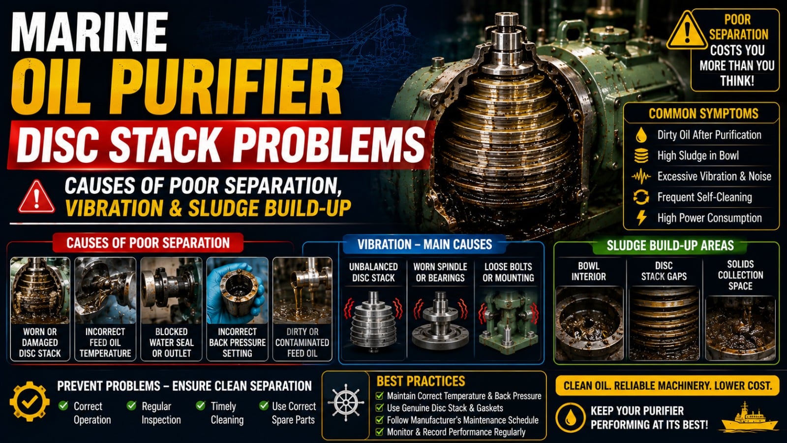
Introduction
In modern shipboard machinery spaces, the centrifugal oil purifier (separator) is the primary safeguard protecting marine diesel engines from abrasive wear and fuel system failure. With contemporary heavy fuel oil (HFO) and Very Low Sulfur Fuel Oil (VLSFO) carrying elevated levels of abrasive catalytic fines (aluminum and silicon oxides), asphaltenes, and water, consistent separator performance is non-negotiable.
The heart of any centrifugal separator—whether Alfa Laval, Mitsubishi Kakoki, or GEA Westfalia—is the disc stack assembly. When the disc stack fouls, distorts, or loses mechanical compression, separation efficiency degrades instantly. Dirty fuel bypasses the settling zone and enters the daily service tank, leading to rapid fuel injection pump seizure, exhaust valve blow-by, and severe cylinder liner scuffing. Recognizing disc stack problems early prevents costly downstream engine overhauls.
How Disc Stack Separation Works
Centrifugal separation accelerates the natural gravity settling process by thousands of times ($G$-force typically ranging from 5,000g to 8,000g at 6,000–9,000 RPM). Understanding the physics of the disc stack clarifies why minor internal faults ruin performance:
- Stratification into Thin Layers: A typical marine purifier disc stack contains 60 to 150 conical stainless-steel discs stacked at an angle of 45° to 60°. Spacer ribs (caulks) maintain a minute clearance of 0.4 mm to 0.8 mm between adjacent discs. This design stratifies the oil into ultra-thin laminas, reducing the travel distance particles must settle before hitting a surface to fractions of a millimeter.
- Two-Phase Counterflow Separation: Under centrifugal force, dense heavy particles (sludge, sand, cat-fines) and free water travel outward along the underside of the conical discs toward the bowl periphery. The purified light oil phase flows inward along the upper surface toward the center, exiting via the pairing disc (centripetal pump).
- Sludge Discharge Concept: Accumulated sludge at the bowl periphery is periodically ejected through discharge ports when operating water actuates the sliding bowl bottom. If the disc channels leading to this zone choke with hard carbon, the separation equilibrium collapses.
Common Disc Stack Problems & Failure Modes
Shipboard inspections consistently reveal specific recurring failures within the disc stack assembly:
1. Carbon and Asphaltic Sludge Baking
When fuel preheating temperatures fluctuate or oil is subjected to excessive thermal stress (temperatures exceeding 98°C–100°C in the heater), unstable asphaltenes precipitate. Hard, baked carbon deposits accumulate in the inter-disc spaces, choking the narrow flow passages and drastically reducing the effective separation area.
2. Uneven Sludge Accumulation and Rotational Imbalance
If sludge discharge is incomplete—often caused by blocked operating water nozzles, worn distributor O-rings, or short discharge timer cycles—sludge remains stuck on one side of the disc stack. Spinning an unbalanced 80 kg bowl assembly at 7,500 RPM generates extreme centrifugal imbalance, triggering severe vibration alarms.
3. Damaged, Dented, or Warped Discs
Discs are precision-pressed components. Forcing discs apart with screwdrivers during cleaning, dropping them onto steel floor plates, or overtightening the bowl hood deforms their conical geometry. Warped discs create unequal flow paths, causing oil to channel through wide gaps at high velocity without undergoing separation.
4. Worn or Missing Spacer Caulks
The micro-caulks spot-welded onto each disc maintain the exact inter-disc distance. When caulks corrode or break off due to vibration, adjacent discs collapse against each other. This causes local flow starvation and forces dirty oil to bypass the stack entirely.
5. Insufficient Disc Stack Compression Height
Over thousands of operating hours and repeated maintenance cycles, discs settle and caulks wear slightly. If the overall stack height falls below the manufacturer's specified compression limit, the discs will vibrate and chatter against one another under load, causing fretting corrosion and turbulent oil bypass.
Warning Signs of Disc Stack Degradation
Watchkeepers and engineers should monitor these key diagnostic indicators:
- High Particle and Water Carryover: Regular onboard fuel testing reveals rising water percentages or elevated cat-fine levels downstream in the service tank despite normal separator throughput settings.
- Elevated Spindle Vibration: Vibration sensors on the vertical spindle housing register increasing amplitudes. Engineers can physically detect excessive shaking on the purifier frame and sight glasses.
- Frequent Automation Alarms: Recurring alarms on control units (e.g., Alfa Laval EPC-50/EPC-60 or Westfalia D-10) indicating "Water in Oil," "Low Discharge Pressure," or "Sludge Discharge Fault."
- Low Sludge Ejection Volume: During automatic or manual de-sludging, the audible "shoot" sound is weak or muffled, and minimal sludge enters the sludge tank, confirming internal choking.
- Pairing Disc Backpressure Fluctuations: Inability to maintain a stable backpressure on the clean oil outlet pressure gauge indicates erratic flow through choked disc channels.
Step-by-Step Inspection & Cleaning Procedure
Follow this systematic overhaul procedure to restore disc stack efficiency:
- Safe Dismantling: Ensure the purifier has completely stopped (run-down time verified) and electrical isolators are locked out. Use dedicated OEM lifting tools and compression jacks to compress the disc stack safely before releasing the lock ring. Never strike the bowl assembly with steel hammers.
- Chemical Soaking (CIP): Submerge the complete disc stack assembly into a dedicated cleaning tank containing an approved decarbonizing solvent or alkaline wash heated to 60°C–70°C. Allow deposits to dissolve for 4 to 8 hours.
- Ultrasonic and High-Pressure Washing: Transfer individual discs to an ultrasonic cleaning bath or wash them using a low-pressure wash gun with nylon brushes. Never use wire brushes, scrapers, or emery cloth, which scratch the polished stainless steel and accelerate future sludge adhesion.
- Disc Stack Compression Check: Reassemble the discs in their original numbered sequence on the distributor. Use the manufacturer's compression gauge to measure the height from the distributor top to the uppermost disc. If the lock ring tightens past its alignment mark without resistance, add intermediate discs per OEM guidelines to achieve correct mechanical pre-load.
- Spindle and Bearing Inspection: While the bowl is removed, inspect the vertical spindle for radial runout using a dial test indicator (allowable TIR typically <0.02 mm). Check upper buffer springs and bottom thrust bearings for pitting or play.
Preventative Maintenance Checklist & Intervals
Interval Maintenance Item Action Required Daily (Every Watch) Operational Parameters Verify inlet temperature (98°C for HFO), oil flow rate, discharge pressure, and feed pump suction vacuum. Weekly Sludge Discharge Verification Initiate manual shoot; inspect sludge tank discharge sound and volume; clean operating water line strainers. 1,500 – 2,000 Hours Intermediate Service Open bowl; chemical soak of disc stack; renew bowl hood seal ring and operating water sliding seals. 4,000 – 8,000 Hours Major Overhaul Complete teardown; vertical and horizontal shaft bearing renewal; disc stack compression recalibration; brake and friction clutch inspection.Disc Stack Troubleshooting Matrix
Symptom Likely Root Cause Immediate Action Permanent Correction Poor separation; cat-fines in clean oil Choked disc channels; incorrect flow throughput Reduce throughput rate; verify pre-heat temperature at 98°C Dismantle and chemically clean disc stack; check disc caulks Severe bowl vibration during operation Asymmetric sludge build-up; damaged discs Stop purifier immediately; do not attempt forced de-sludge Clean bowl thoroughly; inspect spindle runout; renew worn discs Water carryover into clean oil outlet Gravity disc size incorrect; interface broken Check feed oil density/temperature; verify water transducer Fit correct gravity disc nomogram size or recalibrate discharge sensor Oil overflowing through sludge outlet Bowl open; defective sliding bowl seal ring Stop feed pump; check operating water supply pressure Dismantle bowl; renew main seal ring and rectangular dosing seals Lock ring over-tightening past mark Disc stack height loss / caulk wear Do not operate with loose stack Add additional genuine compensation discs to restore pre-loadFrequently Asked Questions
Why must Heavy Fuel Oil (HFO) be heated to exactly 98°C before entering the purifier?Centrifugal separation relies on the difference in density between oil, water, and solid particulates. As HFO is heated toward 98°C, its viscosity drops dramatically and the density differential between oil and water expands, allowing cat-fines and water droplets to separate rapidly through the narrow disc spaces.
What happens if a purifier operates with insufficient disc stack compression?Insufficient compression allows the individual discs to vibrate and chatter against one another under centrifugal force. This produces severe fretting wear on the spacing caulks, creates turbulent fluid bypass channels, and causes uneven particle loading that eventually leads to high spindle vibration and catastrophic bowl unbalance.
Can damaged purifier discs be straightened and reused?No. Purifier discs are engineered with precision conical tapers and hydrodynamically matched spacing caulks. Hammering or mechanically bending a warped disc creates localized stress concentrations and distorts the laminar flow regime. Damaged discs must always be replaced with genuine OEM replacements.
Why should wire brushes never be used to clean separator discs?Stainless steel purifier discs have micro-polished surfaces to facilitate smooth sludge sliding toward the bowl periphery. Wire brushes, scrapers, or abrasive pads create microscopic scratch grooves on the disc surface. Sludge and carbon immediately anchor into these scratches, causing the disc stack to foul twice as fast during subsequent operation.
What is the difference between a purifier and a clarifier disc stack?A purifier disc stack is configured for three-phase separation (oil, water, and solids) and utilizes discs with distribution holes aligned near the outer edge to create a water seal interface. A clarifier stack is designed for two-phase separation (solids from dry oil) and uses blind (unperforated) discs with no water outlet, forcing all fluid through the stack for maximum particulate removal.
How do cat-fines damage engine components if the purifier fails to remove them?Catalytic fines (aluminum and silicon oxide micro-particles from refinery cracking) are extremely hard, abrasive ceramic crystals. If not removed by the purifier disc stack, they embed into the sliding surfaces of fuel pump plungers, fuel injector nozzles, piston rings, and cylinder liners, cutting deep micro-grooves and causing severe abrasive wear in tens of hours.