Introduction
Nothing focuses an engineer's mind like a steering gear fault. A machinery breakdown in the engine room costs money; a steering failure in a traffic separation scheme can end careers and, in the worst cases, lives. Class surveyors know this, port state inspectors know this, and every chief engineer who has stood at the local control wheel while the bridge tried to recall the emergency drill knows it better than anyone.
The good news is that most steering gear faults come from a short list of causes — lost hydraulic pressure, worn pumps, air in the oil, internal leakage, and seal failures. The bad news is that the gear is a safety-critical system with duplicate arrangements, changeover valves, and control interlocks, so finding which half of the system is misbehaving takes method. This guide works through the components, the symptoms, the checks, and the emergency verification you should complete before sailing.
Main Components of a Marine Steering System
Whatever the make — Hatlapa, Tenfjord, Kawasaki, Rolls-Royce, or a rotary vane unit on a smaller vessel — the building blocks are the same:
- Hydraulic power unit: Motor-driven variable displacement pumps, normally two or more for redundancy, each capable of meeting class duty on its own or in the arranged combination.
- Rams and tiller (or rotary vane): In ram-type gears, pistons press against a tiller arm on the rudder stock. In vane units, a rotor turns inside a fixed stator chamber. Same job, different geometry.
- Rudder carrier: Takes the weight of the rudder and the shock loads. Worn carrier bearings show up later as vibration and rudder chatter — problems people blame on the hydraulics.
- Control system: Follow-up control from the bridge through electrical or hydraulic transmission to the pump stroke mechanism, with non-follow-up (NFU) push-button control as backup and local control at the gear itself.
- Hydraulic reservoir: With level alarms, temperature indication, and breathing arrangements. Low level is the first thing many alarms check for a good reason.
- Valves and protection: Changeover valves between pumps, bypass and relief valves protecting the circuits, cross-connections that must be correct for the operating mode, and filters on the make-up and boost side.
SOLAS frames the performance you must achieve: the main steering gear swings the rudder from 35° on one side to 30° on the other in not more than 28 seconds at deepest seagoing draught and maximum service speed, and the auxiliary gear moves it 15° to 15° in 60 seconds. Those numbers are not paperwork — they are the yardstick for every timing test you run.
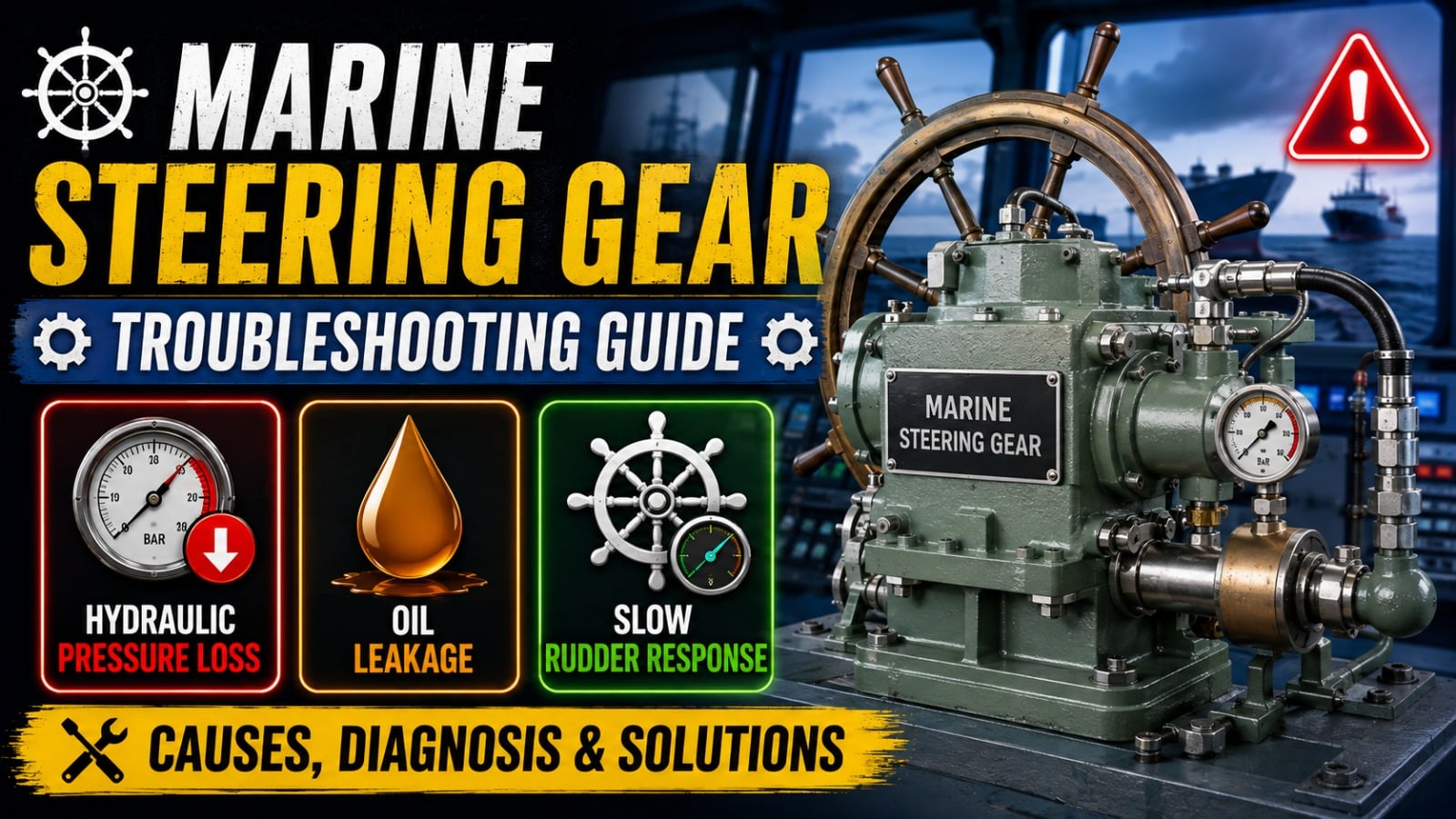
Slow Rudder Response
Rudder that lags the wheel, crawls through midships, or cannot meet the 28-second timing has a mechanical reason, and the pump room gauges will tell you which one.
Low Hydraulic Pressure
Check each pump individually with the changeover arrangement correctly set. Pressure that falls short on one pump but holds on the other isolates the problem to that pump or its suction. Low pressure on both pumps points elsewhere — relief valves set low or passing, bypass valves not fully closed, or a control system not driving the pumps to full stroke.
Pump Wear
Variable displacement axial piston pumps lose output gradually. The plant still works in port with the sea quiet, then fails the full-sea-speed timing test because the worn pump cannot hold displacement against working pressure. Rising oil temperature at steady load is the quiet companion of internal pump leakage. Replacement parts or a reconditioned pump assembly restore the margin.
Air in the Hydraulic Lines
Air compresses; oil does not. Spongy rudder movement, gauges that flutter, and pumps that sound like gravel are the giveaway. Air enters through low reservoir level, a suction leak, or after maintenance that was not properly vented. Bleed the high points with the system circulating slowly, top up with the correct grade, and find the entry path — otherwise the air comes back.
Internal Leakage
Ram piston seals, valve seats, and worn pump internals leak oil across the pressure boundary. The classic picture: pump running continuously at steady pressure, oil temperature climbing, rudder drifting off the ordered angle with the pump at neutral. A rudder that cannot hold position against a moderate sea usually has internal leakage, not an electrical fault.
Hydraulic Oil Leakage
External leaks announce themselves on the reservoir level alarm or as oil in the bilge below the gear; internal ones hide behind a normal-looking level and show up as performance loss. Work the list:
- Ram seals: The most common external leak, especially after long service or a drydock where the rams sat exposed. Check weep holes and drip trays. Renew seals in sets — a mixed set of old and new seals fails early.
- Pump shaft seals: A weeping shaft seal on a running pump loses oil continuously and pulls air when the pump draws vacuum on its suction — leakage and aeration together.
- Piping, flanges, and bulkhead penetrations: Vibrating pipework works fasteners loose; bulkhead passage glands weep after hull movement. Walk the whole circuit with a torch and a rag, top to bottom.
- Valve blocks and instrumentation: Gauge roots and transmitter fittings leak invisibly under insulation or behind covers. Salt and oil dust mark the spots.
- Reservoir and coolers: Cooler leaks pass oil to the sea water side — check the cooler outlets for sheen where the arrangement allows.
Internal leakage deserves respect because it disguises itself. Two rams with bypassing piston seals still move the rudder — just slower, hotter, and with less authority than class expects. When response times drift toward the SOLAS limits, strip and prove the seals rather than adjusting relief valves to mask the loss.
Excessive Steering Noise
Noise is the pump telling you about its suction long before it fails. Cavitation from a choked suction strainer, cold thick oil at start-up, or a reservoir running low produces a crackling, marbles-in-the-pump sound and pits the pump internals. Aeration — air drawn through a leaking suction joint or a return line discharging above the oil surface — makes a smoother but steadier racket and gives the same spongy rudder feel as free air in the lines.
Not all noise is hydraulic. A worn rudder carrier bearing knocks in rhythm with rudder movement; loose coupling bolts click at each reversal; relief valve chatter snaps at a fixed pressure. Separate hydraulic noise from mechanical noise by listening at the pump, the valves, and the carrier in turn while someone works the rudder slowly port to starboard.
Unequal Rudder Movement
Rudder that moves briskly to port and sluggishly to starboard — or stops at slightly different angles each side — narrows the suspects quickly:
- Control feedback error: The follow-up transmitter and receiver drifting out of alignment makes the pump return to stroke before the rudder reaches the ordered angle. Check repeater against rudder angle indicator at the gear, then against the actual rudder.
- Relief valve settings: Valves that have been "adjusted" independently let one side develop full pressure while the other lifts early. Verify against maker settings with a test gauge, not against what feels right.
- Uneven internal wear: One ram circuit leaking more than its partner gives asymmetric authority. Compare pressures per side with each pump in turn.
- Cold oil or partially choked suction on one pump: In duplicated arrangements, each pump feeds the same rudder through its own circuit — a problem in one shows on one direction of travel more than the other until the changeover is proven.
Hydraulic Pressure Checks
- Fit calibrated gauges at the test points — the plant's own gauges have their own history. Record pressures for each pump alone, then in the combined mode the maker specifies.
- Compare against the design figures on the maker's plate, not against last month's log. Working pressure at the rams, relief setting, and boost/make-up pressure each have a number.
- Test relief valves properly: Slow-load the circuit per the maker's procedure with the rudder against its stops where the design permits, and watch where the valve lifts. A relief valve lifting below setting steals performance; one stuck closed transfers shock loads to the rams and stock.
- Check pump displacement control: Order full stroke from the bridge and confirm the stroke mechanism travels fully — a control rod that stops short reduces output on both directions proportionally.
- Verify the changeover and crossover valves: The correct valve line-up for single-pump, two-pump, and emergency modes should be posted at the gear and match reality. Half-open cross-connections create leakage paths that no pump can overcome.
Inspection Procedure
- De-energise and make safe. Stop pumps, secure electrical supplies, hold the rudder with the mechanical stops or lock the pump stroke, and warn the bridge in port. Stored pressure in accumulators (where fitted) must be vented per procedure.
- Reservoir first. Oil level, temperature, water and sediment check from the drain, breather condition. Sample oil for lab analysis — particle count, water content, viscosity — at every opportunity.
- Filters and strainers. Check differential indicators; clean or renew elements. Inspect what you remove — metal particles in a suction strainer are a pump autopsy done early.
- Pumps. Shaft seal condition, coupling bolts and rubber elements, mounting bolts, unusual wear patterns on the stroke mechanism, case drain flow where fitted (a rising case drain flow is an early wear tell).
- Rams, tiller, vane unit. Seal weeping, rod scoring, tiller bolt torque, carrier bearing clearance checks per the class procedure, and greasing arrangements actually delivering grease.
- Valves and pipework. Relief, bypass, and changeover valves for seating and settings; supports and clips complete; flange bolts tight; no chafed or vibrating spans.
- Control and alarms. Follow-up and NFU from bridge and locally, power failure alarms, pump overload, low level, and high temperature alarms — function-test, do not just note the lamps light.
- Full movement test and timing. Port 35° to starboard 30° (or the class arrangement for the vessel), timed, for each pump and in combination. Log the numbers; a timing trend line predicts failure before the alarm does.
Steering Gear Troubleshooting Table
Symptom Possible Cause Check Slow rudder movement, fails timing test Worn pump losing displacement; internal leakage Pressure per pump at load; oil temperature trend; case drain flow Rudder drifts off ordered position Internal leakage past ram seals or bypass valve Pump activity at neutral; ram seal inspection; bypass valve seating Reservoir level falling, no visible leak Internal leakage or cooler passing oil to sea water Check cooler outlets for sheen; inspect weep holes and trays Spongy response, fluttering gauges Air in system; suction leak or low level Bleed high points; check reservoir level and suction joints Pump crackling/noisy at start Cavitation from choked strainer or cold oil Suction strainer condition; oil temperature; warm-up procedure Knock following each rudder reversal Worn rudder carrier bearing; loose coupling Carrier clearance measurement; coupling bolt check Full pressure to one side only Relief valve lifting early on one circuit Relief settings with test gauge against maker figures Rudder stops short on one side Follow-up feedback misalignment Compare ordered vs actual angle; realign transmitter/receiverEmergency Checks Before Sailing
SOLAS requires the steering gear checked and tested within 12 hours before departure, and for good reason — most casualties trace back to a changeover that would not change over, or an alarm that had been accepted as normal. A proper pre-sailing routine:
- Run every pump. Main and auxiliary, each alone, through a full port-to-starboard movement with timing noted. Two-pump combination if that is the sea mode.
- Test every control path. Bridge follow-up, bridge NFU, local control at the gear. Change between them; prove each one actually drives the rudder.
- Prove the changeover valves. Operate them for real. A changeover valve that has not moved in a year is a valve that will not move the day you need it.
- Confirm the alarms. Power failure to each unit, overload, reservoir low level, oil temperature. Accept no alarms in a masked or ignored state.
- Check the emergency power arrangement that feeds the steering gear, and the alternative supply where fitted.
- Agree the communication routine between bridge and steering flat for emergency local steering, and make sure the rudder angle repeater at the gear reads true.
- Top up and record. Reservoir level, oil temperature, any make-up added since last port. Rising make-up consumption is a leak report the level alarm has not caught yet.
Worn pumps, seal kits, ram components, and complete reconditioned power units for the common marine steering gears are part of our stock programme — see our hydraulic pumps and motors supply or send us your steering gear enquiry with the pump type and part numbers.
Frequently Asked Questions
How often must the steering gear be tested before departure?
Within 12 hours before departure, per SOLAS Chapter V Regulation 26. The test covers main and auxiliary steering gear, local and emergency control arrangements, alarms, and the emergency power supply. Keep the record — port state inspectors ask for it, and it is the first document referenced after any steering incident.
Why does the rudder respond slowly even though both pumps are running?
Two pumps do not double speed on every plant — and two worn pumps are worse than one healthy one. Check pressures at each pump under load, oil temperature, and whether relief or bypass valves are passing. Air in the system and a mis-set changeover valve give the same complaint with perfectly good pumps.
What oil should be used in a marine steering gear, and can I mix grades?
Use the grade on the maker's plate — typically a high-grade anti-wear hydraulic oil meeting the viscosity and cleanliness spec listed in the manual. Do not mix grades or brands on a top-up without checking compatibility; viscosity mismatch changes pump performance and the record of cleanliness you have built in the reservoir.
How do I know if my steering pump is worn out?
Trend three numbers: working pressure at load, oil temperature at steady operation, and case drain flow where the pump has one. Displacement loss shows as falling pressure capability, rising temperature, and growing drain flow long before the rudder fails a timing test. Strip inspection at the overhaul interval confirms what the trend says.
Is it acceptable to adjust the relief valve to gain faster rudder movement?
No. Relief settings exist to protect the rams, stock, and structure from shock loads. Faster movement must come from the pumps delivering proper displacement with the correct pressure. If relief valves seem to be the only way to meet timing, the gear has internal leakage or pump wear, and that is the fault to fix.
What causes the steering gear to overheat the hydraulic oil?
Internal leakage dumping high-pressure oil to return — through worn pump internals, passing seals, or relief valves — converts pump work into heat continuously. Continuous pump running against a leaking circuit is the classic picture. Find the leak path; adding a cooler to a leaking system only hides the symptom.
Why check the rudder carrier bearing when the fault seems hydraulic?
Because carrier wear produces knocks, uneven movement, and vibration that get blamed on the hydraulics — and because a failing carrier loads the rams and stock in ways the hydraulic system was never designed for. Measure clearance at every drydock and whenever movement feels anything other than smooth.